
FDM, fused deposition modelling
FDM 3D printing service: parts up to 1000 mm, from 1 calendar day
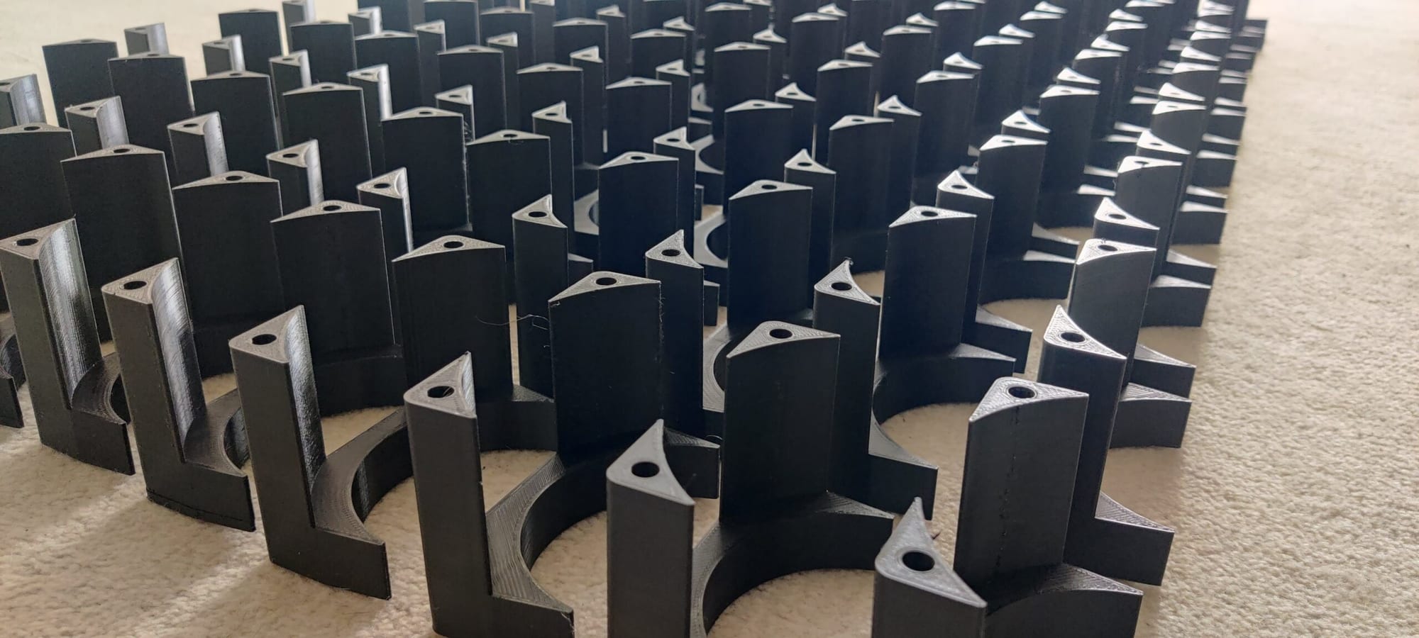
Large, tough functional parts, jigs and fixtures.
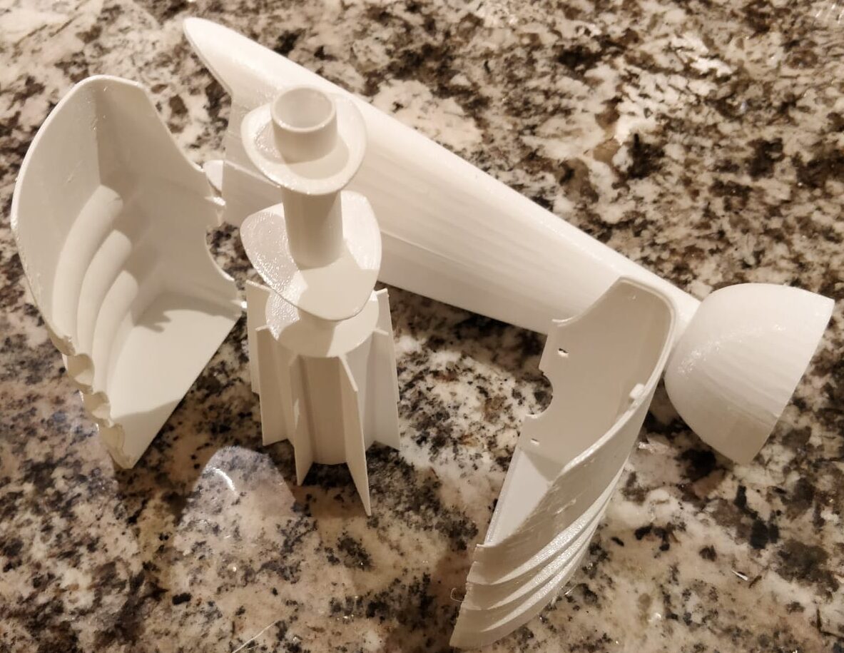
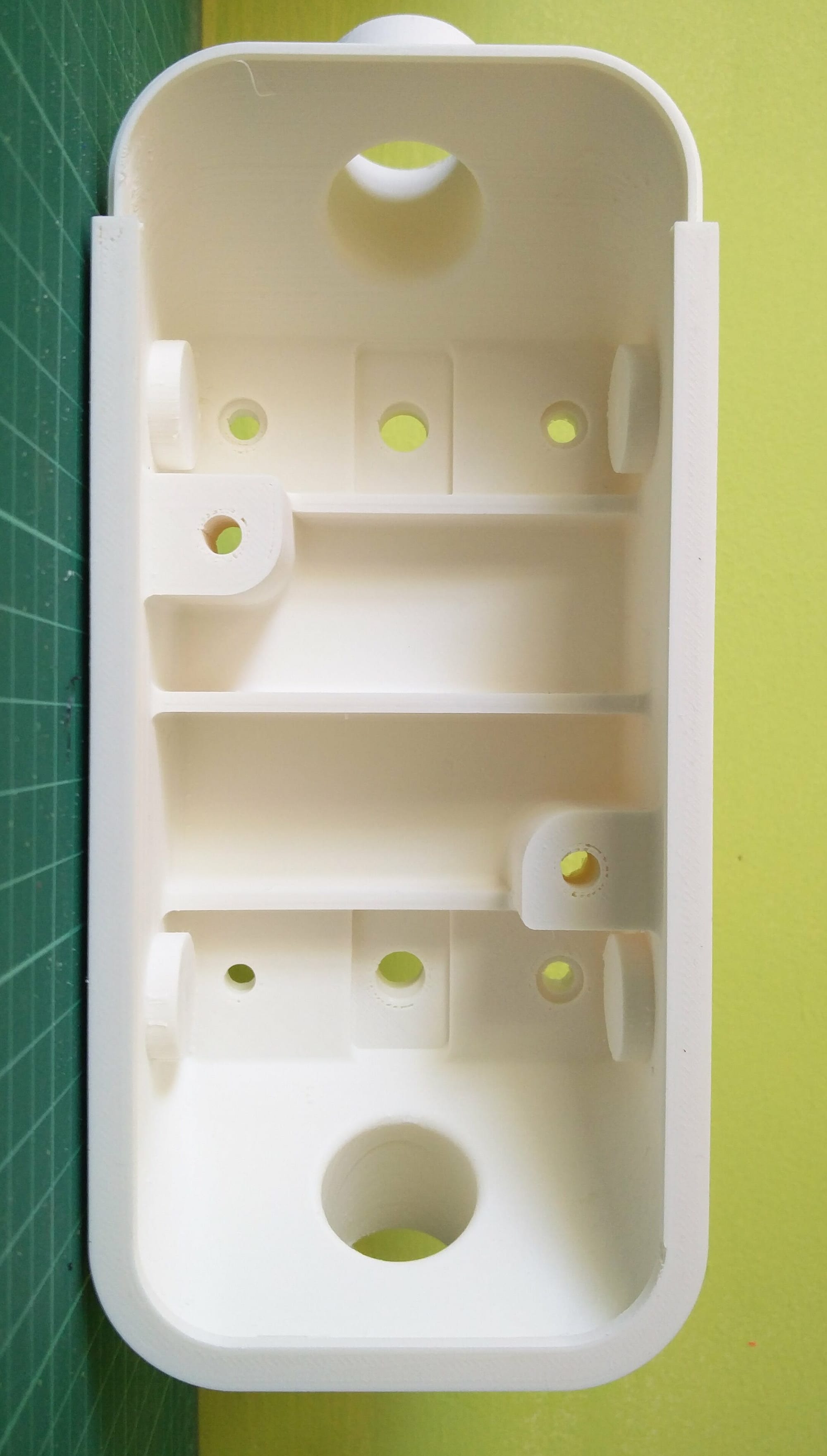
Our UK FDM 3D printing service builds parts up to 1000 mm from thermoplastic filament, laid down layer by layer. It is our only process for parts above 350 mm and suits jigs, fixtures, prototypes and low-volume production.
- Tolerance±0.5% (min ±0.3 mm)
- Lead timeFrom 1 calendar day
- Build volumeEnquire about larger projects: we may be able to accommodate them. We also offer technologies beyond the four processes listed.1000 × 1000 × 1000 mm
| Build volume | 1000 × 1000 × 1000 mm | stated |
|---|---|---|
| Tolerance | ±0.5% (min ±0.3 mm) | stated |
| Layer height | From 50 microns | stated |
| Lead time | From 1 calendar day | stated |
| Minimum wall | 1.0 to 1.2 mm | typical |
| Materials | PLA, PETG, ABS, ASA, TPU, nylon, carbon-fibre PETG, ULTEM | process |
Larger builds are made at our Devon production site: send the drawings for a quote.
FDM process steps
- 01Review
An engineer checks wall thickness, overhangs, tolerances and material suitability.
- 02Prepare
The model is sliced and oriented for strength, surface finish and support strategy.
- 03Print
Filament is melted and deposited layer by layer, from 50 micron layer height.
- 04Finish
Supports come off and the surface is finished to the agreed specification.
- 05Inspect
Parts are checked against the drawing and the stated tolerance before dispatch.

When to use FDM
What FDM suits
- Functional prototypes and end-use parts in engineering thermoplastics
- Jigs, fixtures, tooling and assembly aids
- Parts up to a metre in each direction
- Single parts to batches of thousands, built straight from CAD
- Parts where toughness and cost matter more than a cosmetic surface
Also consider
- Very fine detail or the smoothest surfaces: SLA, from 10 microns
- Uniform-strength nylon parts with internal channels: SLS
- Multi-material or multi-colour parts with fine detail: PolyJet
- Clear or transparent parts: SLA
FDM materials
Eight materials are standard and five more are quoted on request. PETG is the default.
| Material | Best for | Cost |
|---|---|---|
 PLAPolylactic acid | Form-fit models, visual prototypes, quick iterations | £££££Standard |
 PETGGlycol-modified polyester | General-purpose functional parts, chemical contact | £££££Standard |
 ABSAcrylonitrile butadiene styrene | Impact-loaded parts, anything you sand, glue or paint | £££££Standard |
 ASAAcrylonitrile styrene acrylate | Outdoor end-use parts, UV exposure, around 100 °C | £££££Standard |
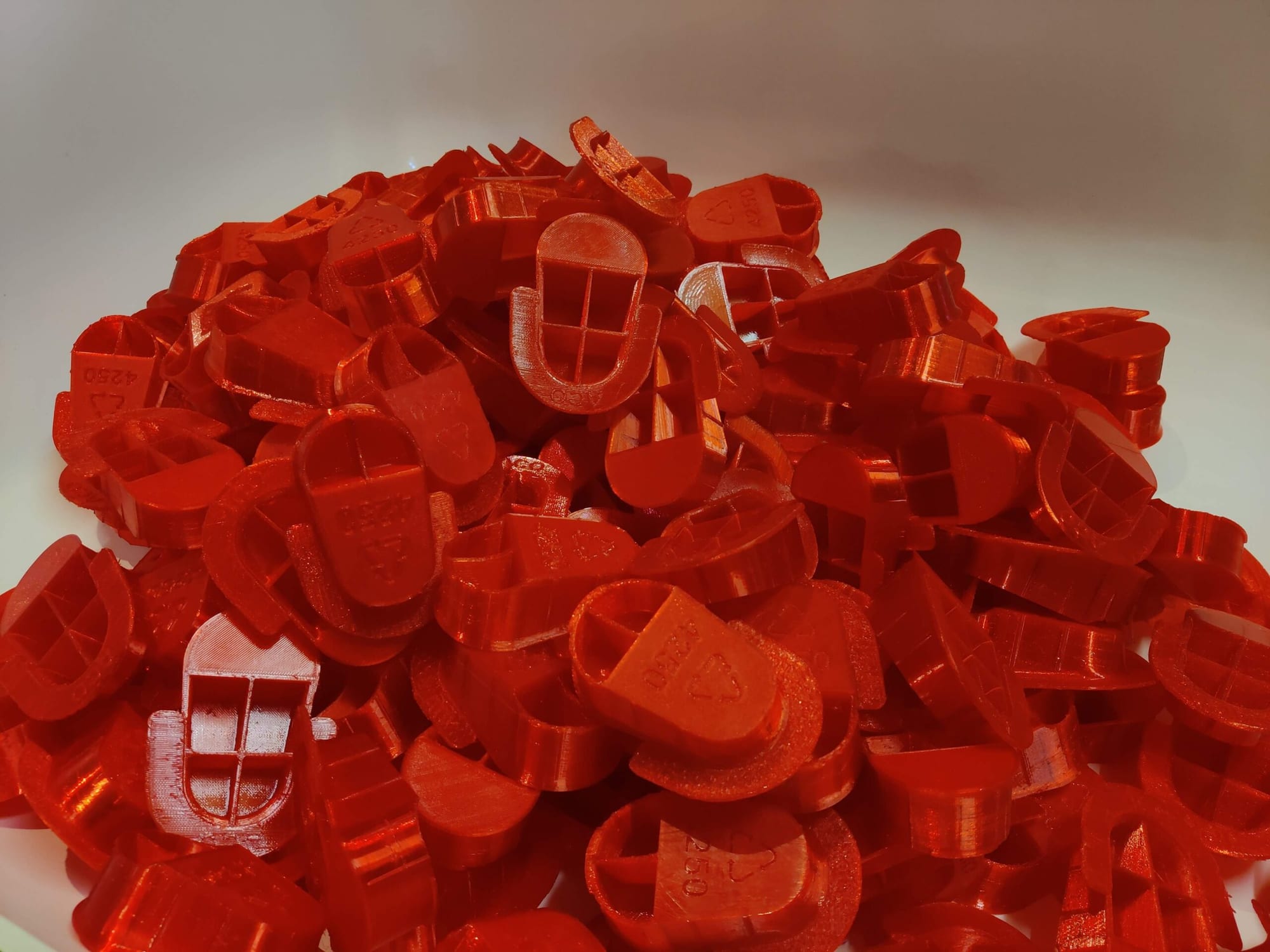 TPUThermoplastic polyurethane, 95A | Seals, grips, bumpers, anything that must flex | £££££Standard |
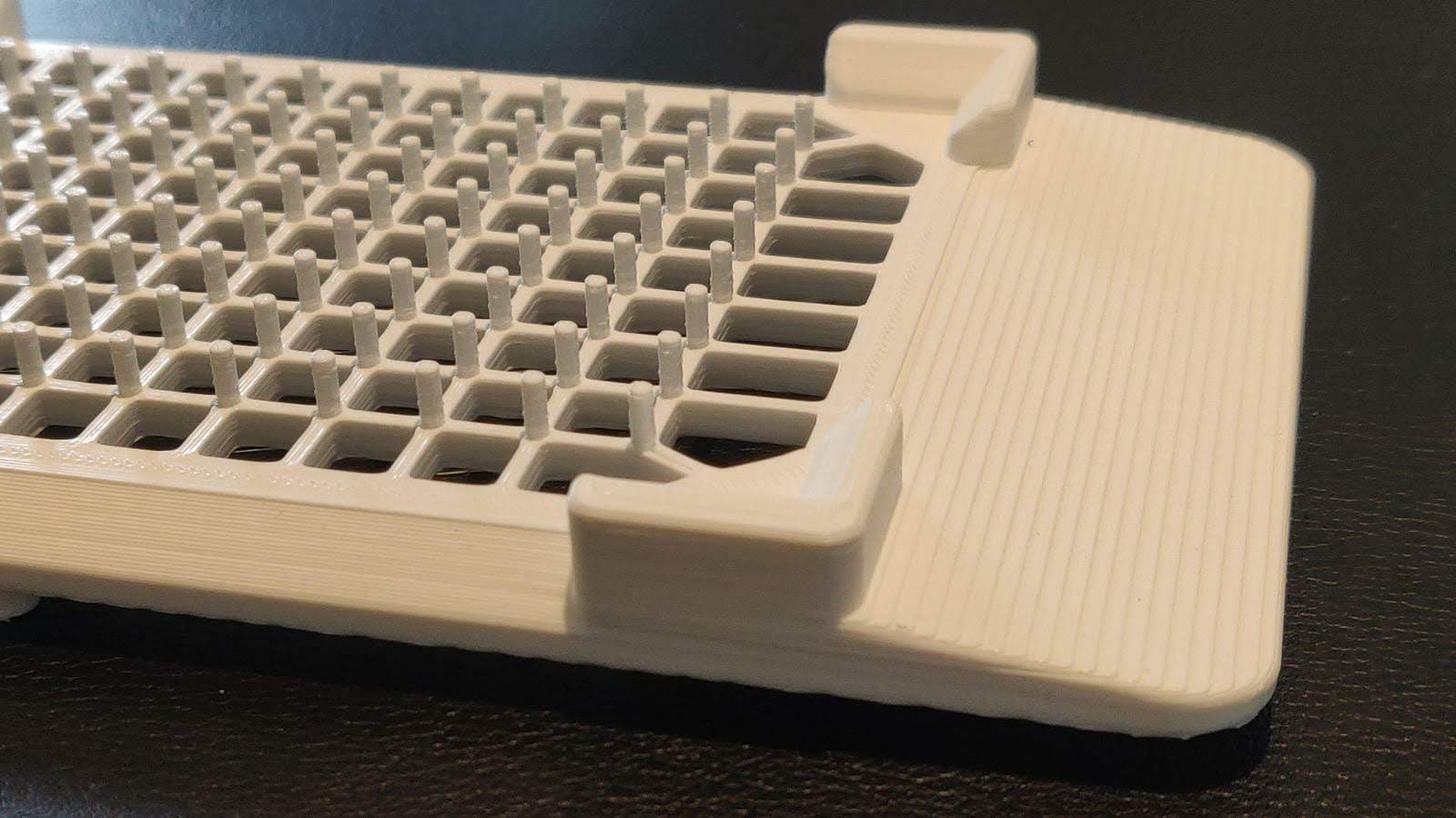 NylonPolyamide (PA12) | Wear parts, moving parts, strong parts with some flex | £££££Standard |
| Fire-resistant PETGFlame-retardant polyester | Electrical housings and enclosures | £££££Standard |
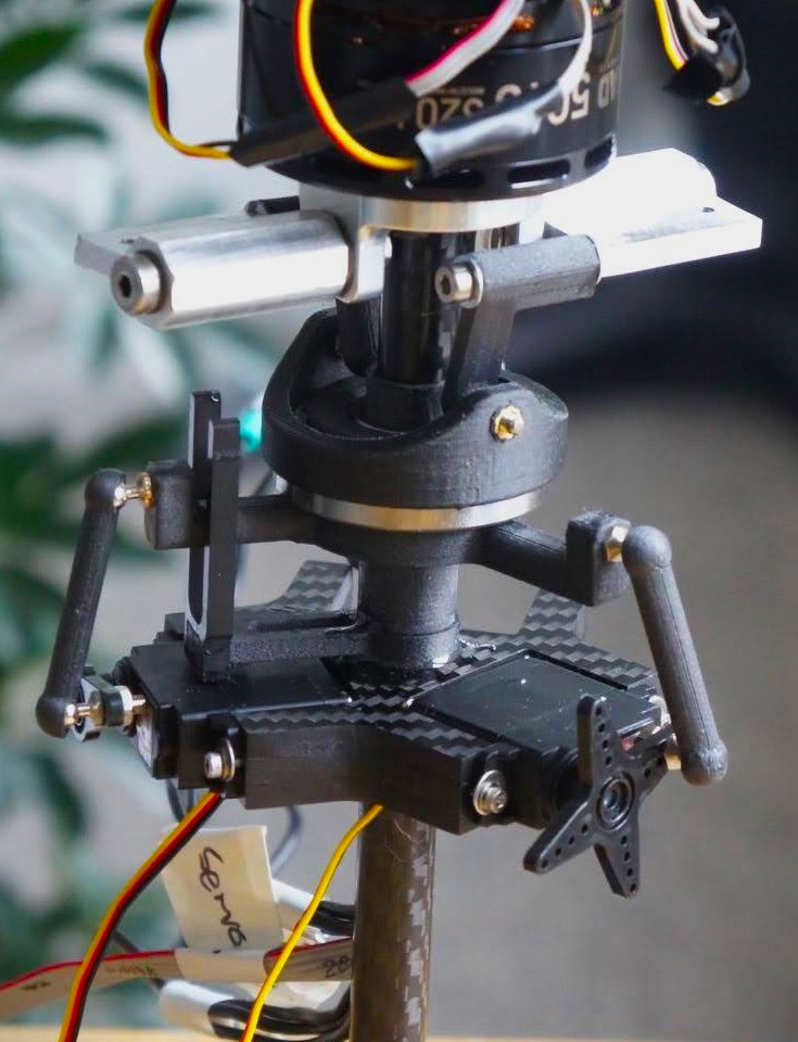 Carbon-fibre PETGCarbon-filled polyester | Stiff, light structural parts, brackets, frames | £££££Standard |
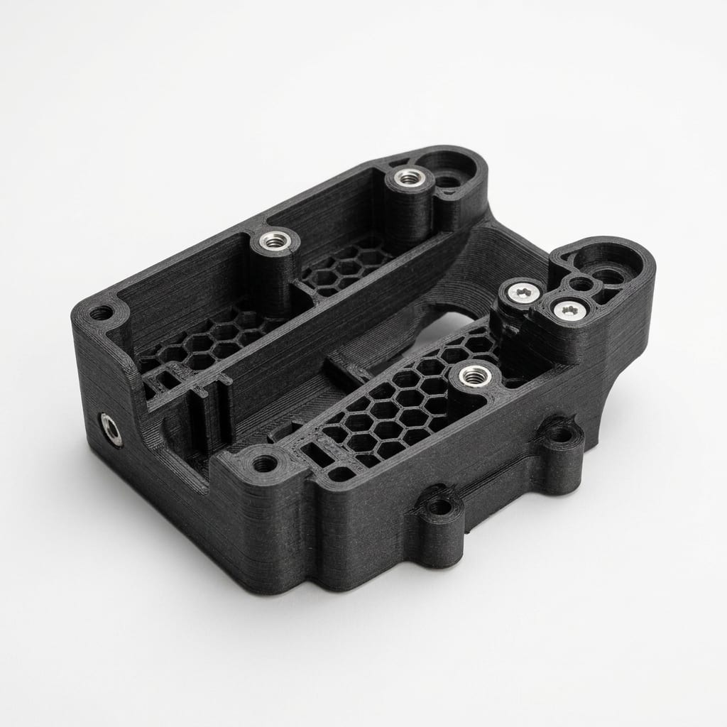 Markforged OnyxCarbon-filled nylon | Strong, stiff, dimensionally stable end-use parts | £££££Standard |
| Stratasys ABSProduction-grade ABS | Dimensionally stable parts with clean detail from soluble supports | £££££Standard |
| ULTEM 9085PEI blend, flame, smoke and toxicity rated | Parts that need a flame, smoke and toxicity rating, heat and chemical exposure | £££££On request |
| ULTEM 1010PEI, highest heat resistance in FDM | Parts at the highest FDM temperatures, very stiff and strong parts, sterilisable grades | £££££On request |
| More materials available. We can source most grades not listed here. Request a material | ||
Cost is relative: more £ means a higher price per part.
FDM design guidelines
Typical values. An engineer confirms them for your part.
| Feature | Key figure | Guideline |
|---|---|---|
| Minimum wall | 1.0 to 1.2 mm | Go thicker where the part carries load. |
| Unsupported overhang | Up to about 45° from vertical | Steeper overhangs take supports, which mark the surface. |
| Bridges | Under about 5 mm | Longer spans take supports. |
| Clearance, mating parts | 0.3 to 0.5 mm | Matches the stated tolerance. |
| Internal corners | Add a fillet | Spreads stress along layer lines. |
| Build-plate edges | 45° chamfer | Gives a clean first layer and an easy release. |
Rules of thumb
- Orient for loadThe bond between layers is the weakest direction, so run the load along the layers.
- Keep bridges shortSpans under about 5 mm print cleanly. Longer spans need supports.
- Chamfer the baseA 45° chamfer on plate-side edges prints cleanly and releases easily.
- Drill small holesPrint holes undersized, then drill or ream to size for a precise fit.
FDM tolerance
Deviation at each nominal dimension: the larger of 0.5% of the dimension or ±0.3 mm.
Comparison with other processes at 100 mm
Calculated from our stated tolerances. Critical dimensions are flagged on the drawing and checked before dispatch.
FDM FAQ
What is the maximum part size for FDM?
1000 × 1000 × 1000 mm. Larger assemblies can be split into sections and bonded. Enquire about larger projects: we may be able to accommodate them.
How accurate are FDM parts?
±0.5% with a minimum of ±0.3 mm. Flag critical dimensions on the drawing and we check them before dispatch.
How fast can I get FDM parts?
From 1 calendar day. The quote shows the lead time for your part.
Which FDM material should I choose?
PETG for most functional parts. PLA suits visual models, ABS suits impact, ASA suits outdoor use, TPU suits flexible parts, and nylon or carbon-fibre grades suit high strength. Tell us the load, temperature and environment and an engineer recommends one.
Is FDM strong enough for functional use?
Yes. Parts are strongest along the layers, so we orient the build to the load path.
Companies that use HenleyPrint3D










Send CAD for an FDM quote
Upload a STEP or STL file for a price and lead time. An engineer confirms material, tolerance and finish before we build. Uploads are secure and confidential.