
Industries / Defence
Defence 3D printing and additive manufacturing for UK and allied European programmes
Prototypes, programme support, research, tooling and batch manufacture for UK defence suppliers and selected European partners. Work is carried out under mutual NDA by a UK engineering team. Request the NDA first, then send the model for a quote.
- Typical items
- Enclosures, payload brackets, UAV airframe components, equipment cases, tooling
- Volumes
- 1 to thousands, with moulding available beyond that
- Processes
- FDM, SLS nylon, SLA for fit models
- Handling
- Mutual NDA before files are shared
- Quality
- Working towards ISO 9001, build record per revision
What we do
Defence capability
The work we do for defence primes and their supply chain, in the order a programme usually needs it.
Prototyping
Fit, form and function prototypes from your model, built under NDA and revised in days as trial feedback arrives.
Programme support
Engineers working alongside your programme: design for manufacture, test planning, documentation and supplier coordination.
Research and development
Lightweight structures, composite armour concepts and materials research, developed with test partners.
Tooling manufacture
Jigs, fixtures, moulds and composite layup tooling, printed and finished in-house.
Batch manufacture
Components from 1 to thousands, built against a frozen revision with a build record.
In-field manufacturing support
Ruggedised, deployable production capability and training so repair parts can be made at the point of need.
Iteration timeline
Typical timeline from model to batch
Calendar days. Part size and finishing change the dates; the quote gives the committed dispatch date.
- Day 0
Model and duty received
STEP or STL plus a note on environment: vibration, shock, temperature range, ingress, handling by gloved operators. We review printability and advise on material and orientation for the stated duty.
- Day 1 to 3
First article, FDM or SLS
A first build in a material chosen for the duty. FDM nylon or carbon-fibre filled for stiff mounts; SLS PA12 where wall sections are thin or the geometry is complex. Checked for fit against your reference hardware.
- Day 3 to 5
Revision from trial feedback
Trials may show a cracked boss, a stiff latch or a cable exiting at the wrong angle. Send the revised model and we rebuild it; with no tooling, a change costs only the rebuild.
- Day 5 to 10
Second and third articles
Orientation, wall thickness and rib layout are tuned. Inserts, gaskets and finishes are specified. Each article is measured against the features you mark.
- Day 10 to 14
Fielding batch
When the design is frozen we build the quantity needed, record the build against the frozen revision, and dispatch. A repeat order uses the same record so the second batch matches the first.
Handling and confidentiality
File and part handling
How confidentiality and traceability are handled on every order.
Confidentiality
- Mutual NDA signed before you share geometry.
- Orders kept out of marketing material, case studies and social posts unless you agree in writing.
- We quote and build from the model and the duty; programme details are not needed.
- Files deleted on request when the order closes.
- Delivery to a UK address, or abroad with customs paperwork prepared.
Quality and traceability
- Working towards ISO 9001. We hold no AS9100 certification, security clearance or ITAR registration.
- Build record kept against the frozen revision, so a repeat order matches the first.
- Dimensional report on the features you mark.
- Parts made in Devon on machines we operate.
- Dispatch date committed in the quote.
Standards
Quality and handling status
What is in place today.
- Working towards ISO 9001
- GDPR-compliant file handling
- NDA on request
- Build and inspection records
Airframe analysis
UAV airframe analysis examples
Three example simulations show the review we apply to airframe parts: stress under flight and landing loads, vibration modes of a mounting bracket, and the mass saved by a lattice-optimised arm. Figures are illustrative; project values come from your load cases and test data.
von Mises stress, MPa. Marker: example allowable, 240 MPa.
- Lift
- Motor thrust
- Payload inertia
- Landing impact
Pull-up, lift and payload inertia scale with load factor.
- Max von Mises
- 402 MPa
- Location
- wing spar
- Margin to allowable
- 0.60
- Wing tip deflection
- 8.3 mm
- Root fitting reaction
- 2.76 W
- Reference weight W
- 4.0 kg (input)
Load paths run from the lift, thrust, payload and impact points into the airframe fitting. The wing spar sees bending, mounts and legs see axial and bending load, the bracket sees truss load. Stress concentrates at the fitting bolts and at joints.
Normalised modal displacement, % of peak.
Whole flange bends about the bolted edge.
- Mode 1
- 394 Hz
- Mode 2
- 751 Hz
- Mode 3
- 1161 Hz
- Hot end
- 60 °C
- Frequency shift
- -4.4 %
Heating the free end softens the part, so each frequency moves down by the amount shown. Holes lighten the plate. Frequencies are display values from a schematic model with 3 lightening holes.
- Mass change
- -37%
- Peak stress change
- +43%
- Margin to allowable
- 1.18
Material is placed along the load path and removed where stress is low. Printed lattice makes shapes like this buildable in one piece. Marker on the stress bar: example allowable, 240 MPa.
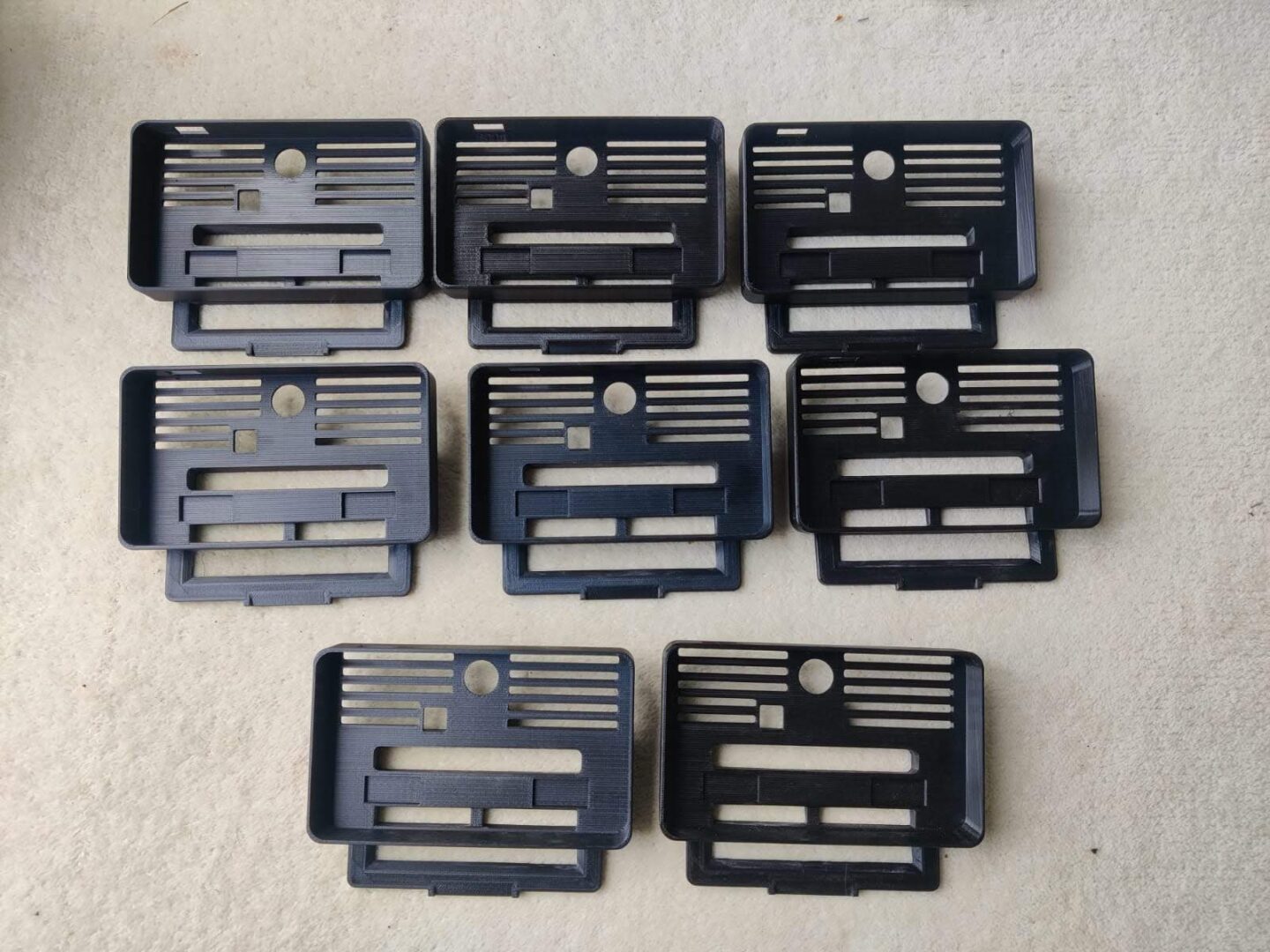
Enclosures
Ruggedised enclosure design guidance
Most defence enquiries are housings for electronics, radios, batteries and sensors.
- Nylon walls of 2.5 to 4 mm give better impact resistance than a thinner shell; ribs add stiffness without adding bulk.
- Use a gasket groove and a printed or machined flange for sealing, and test ingress on a sample before committing a batch.
- Heat-set threaded inserts take repeated service access better than printed threads.
- A sand-blasted or painted finish reduces glare and hides layer lines. Matte finishes are a common request.
- Mounting bosses should be tied into ribs; point-loaded bosses are where trial damage usually starts.
Typical parts
Parts for trials and small fleets
Process shown is the usual fit. Material and process are agreed at review for your duty.
- P-01
Enclosures
Printed shell, insert-fitted, gasketed. Lids designed to be opened many times.
FDM / SLS · PA12, CF-nylon - P-02
Payload brackets
Stiff brackets that position optics, antennas and sensors, iterated until alignment holds.
FDM · CF-nylon - P-03
UAV airframe components
Fittings, arms, motor mounts and bays, lightweighted along the load path.
SLS / FDM · PA12, CF-nylon - P-04
Magnet and equipment cases
Cases with heat-set threaded inserts for repeated service access.
FDM / SLS · PA12 - P-05
Tooling
Jigs, fixtures and trial rigs, built in days and replaced at low cost.
FDM · ABS, nylon
Primes and manufacturing drawings
Experience with UK primes
 Worked closely with UK primes.
- Parts are made in Devon on machines we operate.
- Dispatch date is committed in the quote. A trial revision can often be rebuilt in 1 to 3 calendar days.
- Materials include PA12, carbon-fibre nylon, ABS and ASA.
FAQ
Frequently asked questions
How is my data handled?
We sign a mutual NDA before you share files, build from the model, and delete files on request when the order closes.
How quickly can you iterate a design during trials?
A revised model can usually be rebuilt in one to three calendar days in FDM or SLS. The quote states the dispatch date for each build.
How many units can you supply?
From one part to thousands. For larger volumes we advise whether moulding is the better route.
Which material for a rugged enclosure?
Nylon PA12 (SLS or FDM) and carbon-fibre filled nylon give the best toughness and stiffness. ABS or ASA are lower-cost options for lower-impact housings.
Do you analyse airframe parts?
Yes. We review load paths, fixings and wall sections for brackets and UAV components. The simulations on this page are examples of that approach.
Will our work appear on your website?
Defence orders stay confidential. Nothing is used in case studies or marketing without written agreement.
Related
Related processes, materials and guides
Request an NDA before sending files
Request a mutual NDA through the contact form. Once it is signed, send the model and the duty and we return a quote.