Case study · Industrial
100% infill FDM parts made to a strength criterion
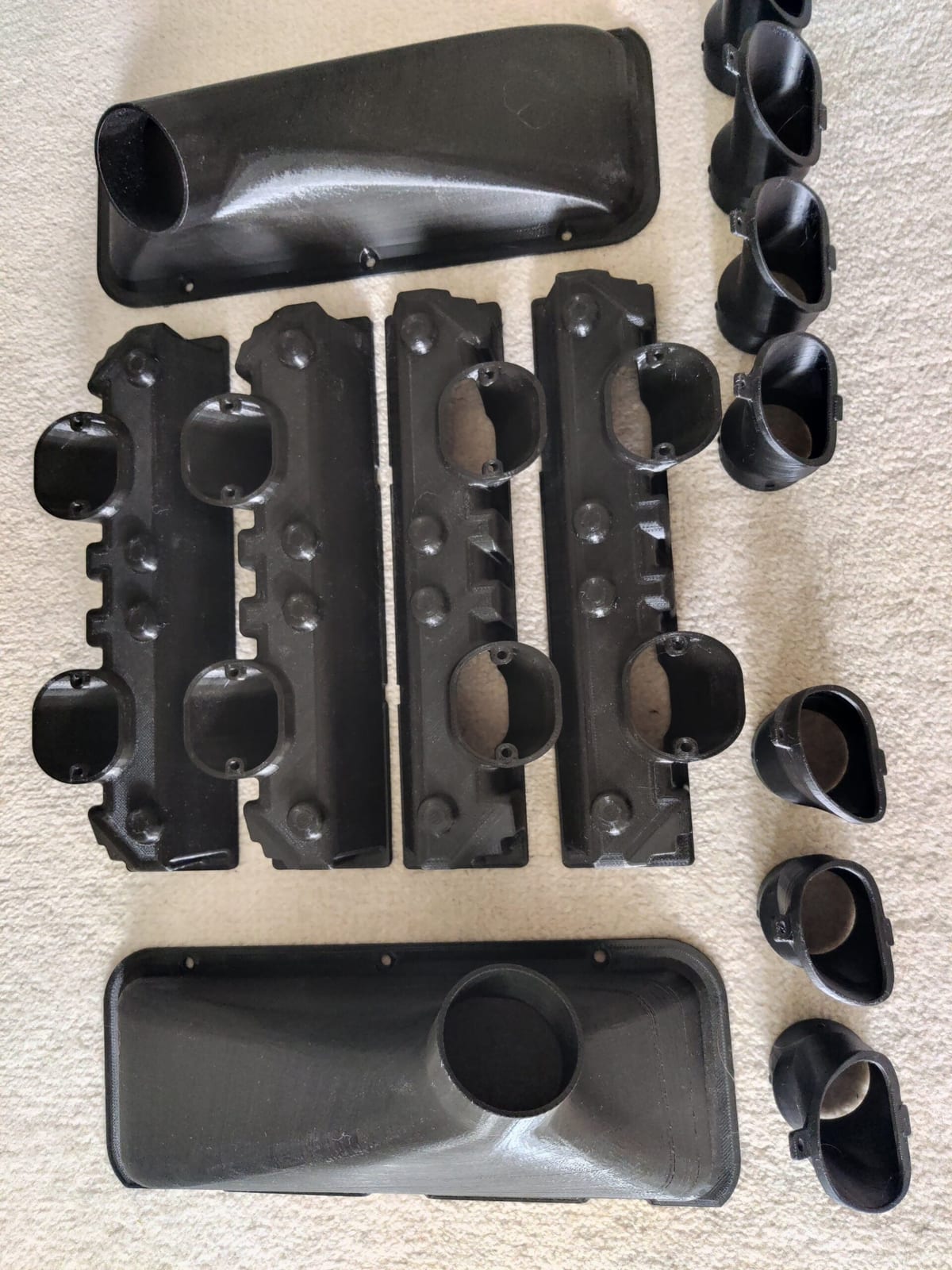
Solid FDM housings, shells and pegs for an industrial customer, printed at 100% infill to meet a strict strength criterion and checked against it before release.
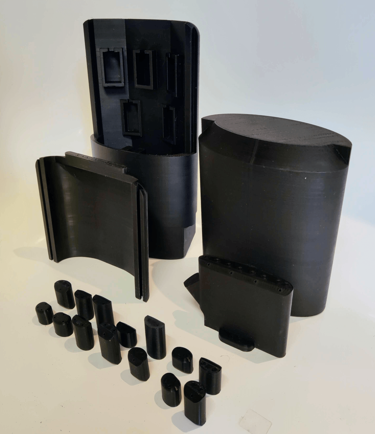
- 1Pocketed housing
- 2Solid oval body
- 3Small solid pegs
Requirements
- R1Strength: meets the stated criterion.
- R2Tolerance: held despite the high material volume.
- R3Evidence: validated before release.
- Meet a strict strength criterion with fully dense printing.
- Hold tight tolerances despite the large material volume.
- Evidence that the parts meet the requirement.
Method
- 01
Solid infill
Fully dense parts for strength and stiffness.
- 02
Tune the process
Settings adjusted to hold tolerance with the high material volume.
- 03
Validate
Parts were checked against the strength requirement before release.
Outcome
- Solid 100% infill parts, giving the highest load capacity FDM allows.
- Parts validated against the strength requirement before release.
Why this process and material
Why 100% infill
Infill density sets how much cross-section carries load. Solid infill removes internal voids and raises stiffness and strength compared with sparse infill.
Why tolerance needs attention
Dense parts shrink and warp more as they cool, because more material is deposited. Compensation and thermal control are part of the setup.
Why validate
Printed strength depends on orientation and layer bonding. Testing against the requirement is the only reliable confirmation.
Summary of the engineering approach
Solid infill removes internal voids, so the whole cross-section carries load and stiffness and strength rise compared with sparse infill. The extra material is the risk: dense parts shrink and warp more as they cool, so settings were adjusted to hold tolerance. Printed strength also depends on orientation and layer bonding, which is why the parts were checked against the strength requirement before release rather than assumed to pass.
Questions about this project
Why use 100% infill?
Infill density sets how much cross-section carries load. Solid infill removes internal voids and raises stiffness and strength compared with sparse infill. It gives the highest load capacity FDM allows.
Why is tolerance harder on solid parts?
More material is deposited, so dense parts shrink and warp more as they cool. Compensation and thermal control are part of the setup.
How was the strength criterion confirmed?
The parts were checked against the strength requirement before release. Printed strength depends on orientation and layer bonding, so testing against the requirement is the only reliable confirmation.
Suggested next steps
Recommendations for taking the part further. None of this is completed work.
- Record the test method and results against print orientation, so the criterion is traceable.
- Compare solid infill with shell-and-rib, to see if the criterion is met at lower mass and print time.
- Look at a stronger material grade if the criterion is raised.